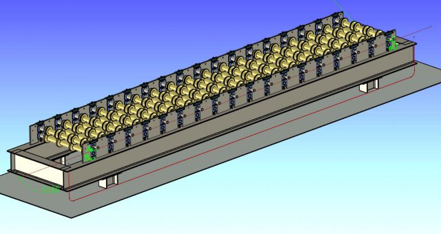
Roofing sheet machinery Installation Steps introduction
Detail steps step 1: Frame level detection and adjustment
Note: The size marked in the picture is the reference size, the customer should adjust according to the actual size;
(1) Material needed: 10mm transparent plastic tube, the length is about 1.5 times that of the large frame.

(2) Fill the water pipe with water without bubbles, and the plastic pipe cannot be discounted or blocked, so that the water is unobstructed.
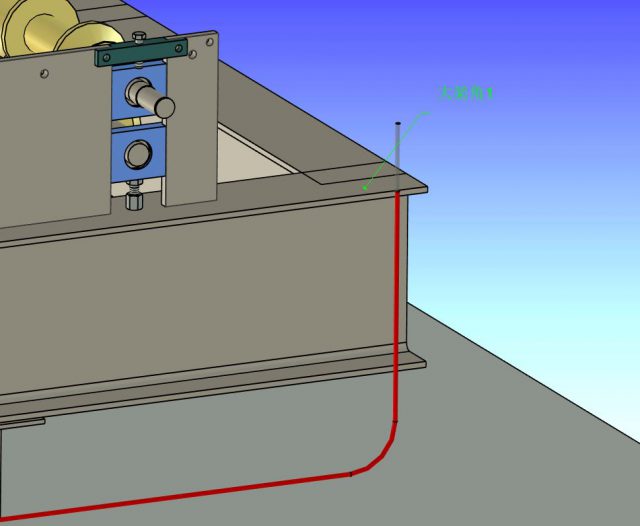
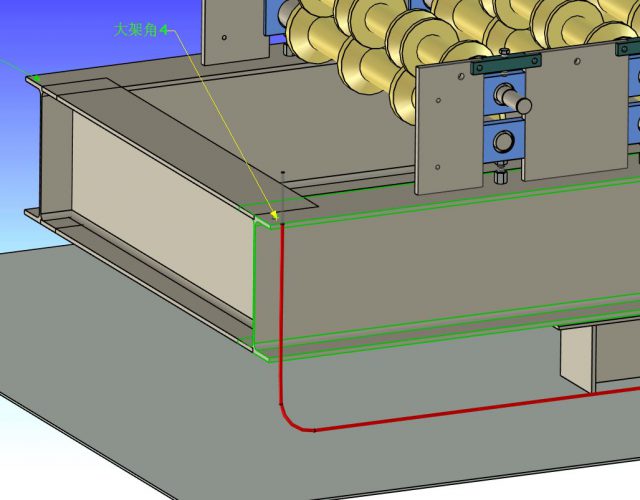
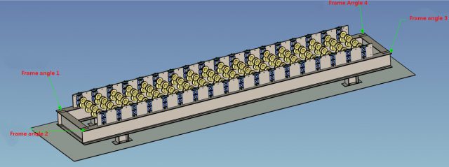
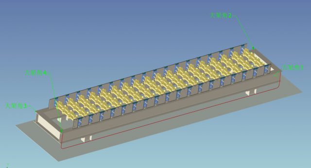
(3) Take 4 corners on the big frame: big frame angle 1, big frame angle 2, big frame angle 3, big frame angle 4.
(4) Measure the large frame angle 1 and the large frame angle 4 at both ends of the water pipe respectively, so that the horizontal lines of the water pipes of the large frame angle 4 and the large frame angle 1 are aligned (red is the water surface)
(5) After aligning the horizontal plane with the large frame angle 1 as the reference, check whether the horizontal plane of the large frame angle 4 is also aligned with the horizontal plane. If there is an error, adjust the height of the large frame to align with the horizontal plane.
(6) After adjusting the big frame angle 1 and big frame angle 4, keep the water pipe of big frame angle 1 still, move the other end of the water pipe to measure the level of the other two corresponding angles, and adjust the height of the big frame to make the other two big angles. The frame angle is the same level as the large frame angle 1.
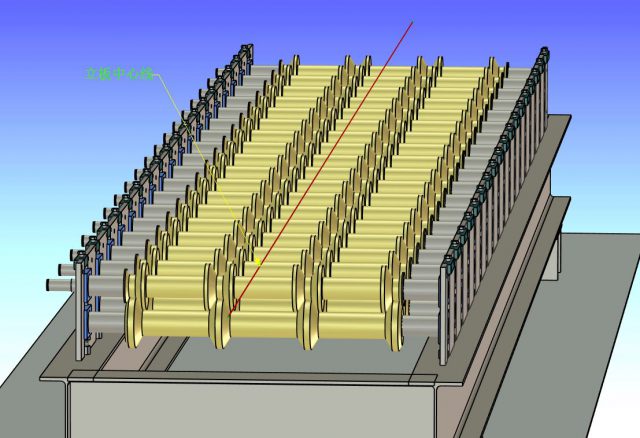
Illustration
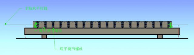
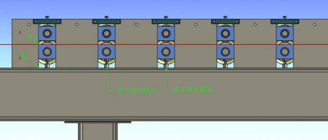
Step 2: Adjustment and measurement of mian shaft level
(1) Take two points at the upper end of the vertical plate and the lower tile box at both ends of the machine, point A point B and the other end point C and D.
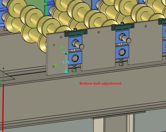
(2)Measure the sizes of A B and C D respectively to make them consistent. If there is an error, adjust the bottom flat screw to make it consistent.
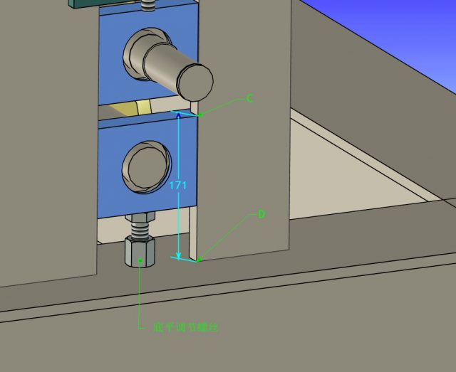
(3) Then draw a line (the red straight line in the figure) across the two points A and C at both ends.
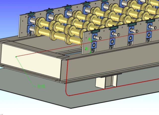
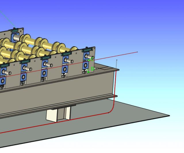
(4)Check whether the upper plane of the middle tile box is in a straight line with the horizontal line of the main axis, and adiust the tile box based on the horizontal line of the main axis, and adjust all to a parallel state.
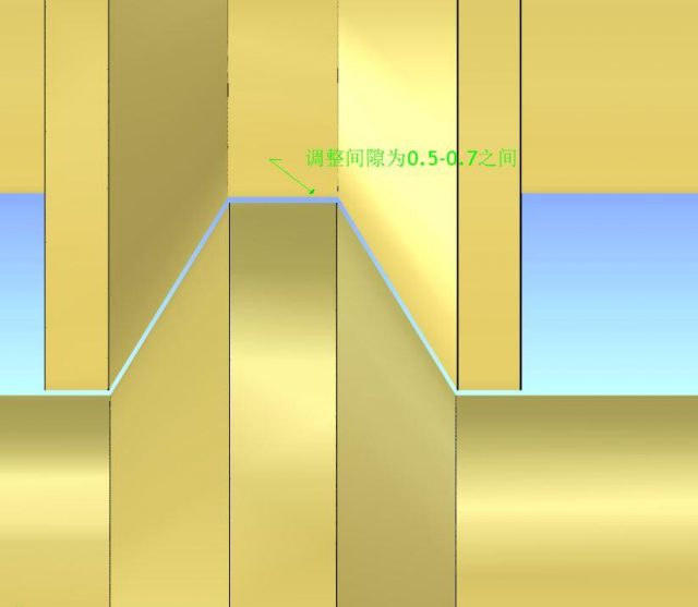
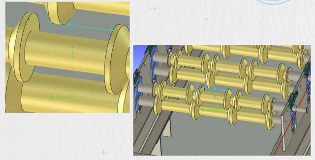
Step 3: Adjust the gap between the upper and lower axle wheels
After adjusting the level of the bottom shaft,adjust the gap between the upper and lower wheels according to the bottom wheel to be consistent between 0.5m m-0.7mm.
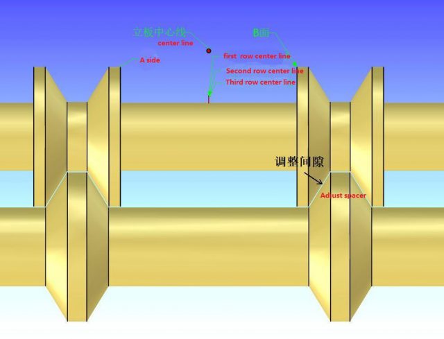
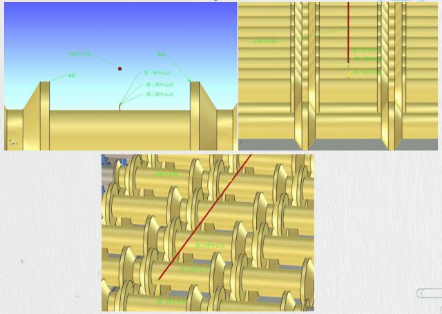
Step 4: main shaft center line adjustments
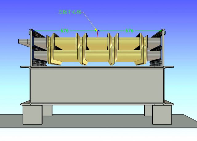
·(1) Draw a centerline of the vertical plate with the vertical plates at both ends as the reference size,and use this as the reference.
(2) Find the center point of the first row according to the size between the middle wheels of the upper shaft in the first row.
(3)Adjust the center point of each row of the axle to align with the center line of the vertical plate as the reference.
Step 5: Solution to the problem of feeding deviation
ln the production process, if the following situations occur:
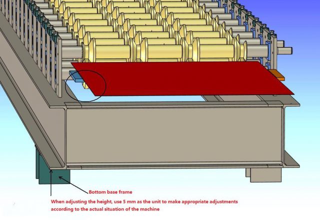
lf the left or right side of the board deviates from the normal position (the position is deviated to the left in the figure), adjust the height of the base under the large frame on the left and the ground .
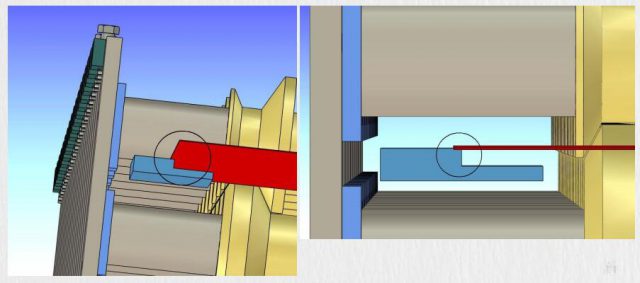
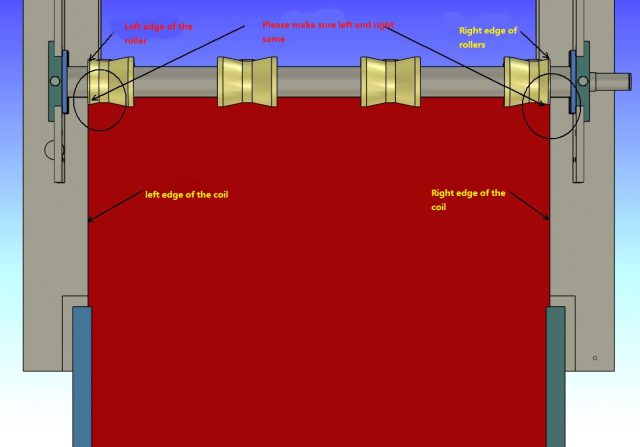
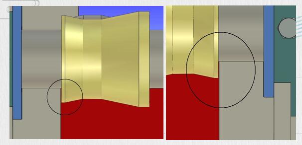
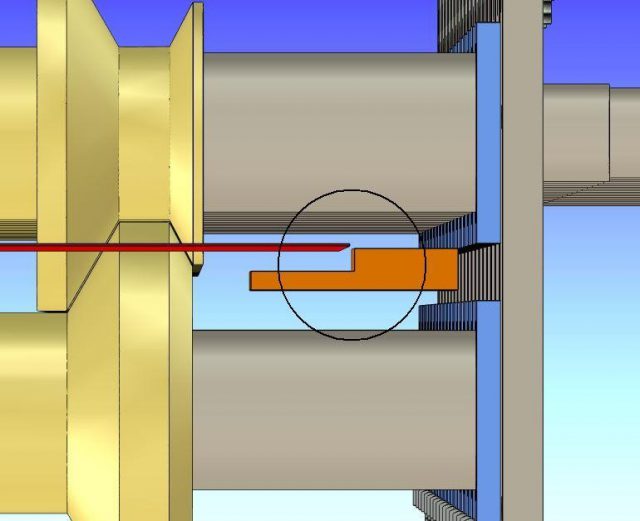
Please make sure the seam exactly like the pictures.
When adjusting the height,use 5 mm as the unit to make appropriate adjustments according to the actual situation of the machine.